Tuesday 28 April 2015

HA7 Task 6

Constraints:


Polygons Vs. Triangles

When a game artist talks about the poly count of a model, they really mean the triangle count. Games use triangles not polygons because most modern graphic hardware is built to accelerate the rendering of triangles.
The polygon count that's reported in a modeling app is always misleading, because the triangle count is higher. Polygons are always converted into triangles when loaded in a game engine. If you're using a polygon counting tool in your modeling app, it's best to switch it to count triangles so you're using the same counting method everyone else is using.
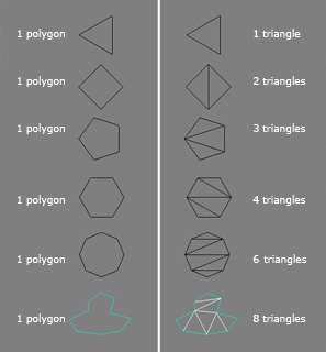
Triangles.jpg
Image by Michael "cryrid" Taylor
When a model is exported to a game engine, the polygons are all converted into triangles automatically. However different tools will create different triangle layouts within those polygons. A quad can end up either as a "ridge" or as a "valley" depending on how it's triangulated. Artists need to carefully examine a new model in the game engine to see if the triangle edges are turned the way they wish. If not, specific polygons can then be triangulated manually.
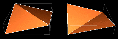
Ridge valley.gif
Image by Eric Chadwick
When using a Normal Map some tools may require an artist to convert the model into all triangles before baking. If the triangles are flipped differently when the model is exported than they were when the normal map was baked, this can cause the final normal-mapped lighting to zig-zag across the model. Triangulating before baking will solve this.
Polygons have a useful purpose for game artists. A model made of mostly four-sided polygons (quads) will work well with edge-loop selection & transform methods that speed up modeling. This makes it easier to judge the "flow" of a model, and to weight a skinned model to its bones. Artists try to preserve these polygons in their models as long as possible.


Triangle Count vs. Vertex Count

Vertex count is ultimately more important for performance and memory than the triangle count, but for historical reasons artists more commonly use triangle count as a performance measurement.
On the most basic level, the triangle count and the vertex count can be similar if the all the triangles are connected to one another. 1 triangle uses 3 vertices, 2 triangles use 4 vertices, 3 triangles use 5 vertices, 4 triangles use 6 vertices and so on.
However, seams in UVs, changes to shading/smoothing groups, and material changes from triangle to triangle... are all treated as a physical break in the model's surface, when the model is rendered by the game. The vertices must be duplicated at these breaks, so the model can be sent in renderable chunks to the graphics card.
Overuse of smoothing groups, over-splittage of UVs, too many material assignments (and too much misalignment of these three properties), all of these lead to a much larger vertex count. This can stress the transform stages for the model, slowing performance. It can also increase the memory cost for the mesh because there are more vertices to send and store.

Rendering:


Rendering is the final process of creating the actual 2D image or animation from the prepared scene. This can be compared to taking a photo or filming the scene after the setup is finished in real life. Several different, and often specialized, rendering methods have been developed. These range from the distinctly non-realistic wireframe rendering through polygon-based rendering, to more advanced techniques such as: scanline rendering, ray tracing, or radiosity. Rendering may take from fractions of a second to days for a single image/frame. In general, different methods are better suited for either photo-realistic rendering, or real-time rendering.

Real-time
Rendering for interactive media, such as games and simulations, is calculated and displayed in real time, at rates of approximately 20 to 120 frames per second. In real-time rendering, the goal is to show as much information as possible as the eye can process in a fraction of a second, i.e. one frame. The primary goal is to achieve an as high as possible degree of photorealism at an acceptable minimum rendering speed (usually 24 frames per second, as that is the minimum the human eye needs to see to successfully create the illusion of movement). In fact, exploitations can be applied in the way the eye 'perceives' the world, and as a result the final image presented is not necessarily that of the real-world, but one close enough for the human eye to tolerate. Rendering software may simulate such visual effects as lens flares, depth of field or motion blur. These are attempts to simulate visual phenomena resulting from the optical characteristics of cameras and of the human eye. These effects can lend an element of realism to a scene, even if the effect is merely a simulated artefact of a camera. This is the basic method employed in games, interactive worlds and VRML. The rapid increase in computer processing power has allowed a progressively higher degree of realism even for real-time rendering, including techniques such as HDR rendering. Real-time rendering is often polygonal and aided by the computer's GPU.

Non Real-time

Animations for non-interactive media, such as feature films and video, are rendered much more slowly. Non-real time rendering enables the leveraging of limited processing power in order to obtain higher image quality. Rendering times for individual frames may vary from a few seconds to several days for complex scenes. Rendered frames are stored on a hard disk then can be transferred to other media such as motion picture film or optical disk. These frames are then displayed sequentially at high frame rates, typically 24, 25, or 30 frames per second, to achieve the illusion of movement.

When the goal is photo-realism, techniques such as ray tracing or radiosity are employed. This is the basic method employed in digital media and artistic works. Techniques have been developed for the purpose of simulating other naturally-occurring effects, such as the interaction of light with various forms of matter. Examples of such techniques include particle systems (which can simulate rain, smoke, or fire), volumetric sampling (to simulate fog, dust and other spatial atmospheric effects), caustics (to simulate light focusing by uneven light-refracting surfaces, such as the light ripples seen on the bottom of a swimming pool), and subsurface scattering (to simulate light reflecting inside the volumes of solid objects such as human skin).

The rendering process is computationally expensive, given the complex variety of physical processes being simulated. Computer processing power has increased rapidly over the years, allowing for a progressively higher degree of realistic rendering. Film studios that produce computer-generated animations typically make use of a render farm to generate images in a timely manner. However, falling hardware costs mean that it is entirely possible to create small amounts of 3D animation on a home computer system. The output of the renderer is often used as only one small part of a completed motion-picture scene. Many layers of material may be rendered separately and integrated into the final shot using compositing software.

Reflection/Scattering - How light interacts with the surface at a given point

Shading - How material properties vary across the surface

HA7 Task 5

3D Development Softwares

3D Studio Max

Autodesk 3ds Max, formerly 3D Studio Max, is 3D computer graphics software for making 3D animations, models, and images. It was developed and produced by Autodesk Media and Entertainment. It has modelling capabilities, a flexible plugin architecture and can be used on the Microsoft Windows platform. It is frequently used by video game developers, TV commercial studios and architectural visualization studios. It is also used for movie effects and movie pre-visualization.

In addition to its modelling and animation tools, the latest version of 3ds Max also features shaders (such as ambient occlusion and subsurface scattering), dynamic simulation, particle systems, radiosity, normal map creation and rendering, global illumination, a customizable user interface, and its own scripting language.


Maya

Autodesk Maya commonly shortened to Maya, is a 3D computer graphics software that runs on WindowsOS X and Linux, originally developed by Alias Systems Corporation and currently owned and developed by Autodesk, Inc. It is used to create interactive 3D applications, including video games, animated film, TV series, or visual effects.


LightWave 

LightWave is a software package used for rendering 3D images, both animated and static. It includes a rendering engine that supports such advanced features as realistic reflection and refraction, radiosity, and caustics. The 3D modeling component supports both polygon modeling and subdivision surfaces. The animation component has features such as reverse and forward kinematics for character animation, particle systems and dynamics. Programmers can expand LightWave's capabilities using an included SDK which offers LScript scripting (a proprietary scripting language) and common C language interfaces.


Cinema 4D

CINEMA 4D is a 3D modeling, animation and rendering application developed by MAXON Computer GmbH in Germany. It is capable of procedural and polygonal/subd modeling, animating, lighting, texturing, rendering, and common features found in 3D modelling applications. Four variants are currently available from MAXON: a core CINEMA 4D 'Prime' application, a 'Broadcast' version with additional motion-graphics features, 'Visualize' which adds functions for architectural design and 'Studio', which includes all modules.


Blender


Blender is a professional free and open-source 3D computer graphics software product used for creating animated films, visual effects, art, 3D printed models, interactive 3D applications and video games. Blender's features include 3D modeling, UV unwrapping, texturing, raster graphics editing, rigging and skinning, fluid and smoke simulation, particle simulation, soft body simulation, sculpting, animating, match moving, camera tracking, rendering, video editing and composting. Alongside the modeling features it also has an integrated game engine.


Sketchup

SketchUp is a 3D modeling computer program for a wide range of drawing applications such as architectural, interior design, civil and mechanical engineering, film, and video game design.
The program includes drawing layout functionality, allows surface rendering in variable "styles", supports third-party "plug-in" programs hosted on a site called Extension Warehouse to provide other capabilities (e.g., near photo-realistic rendering), and enables placement of its models within Google Earth.


ZBrush


ZBrush is a digital sculpting tool that combines 3D/2.5D modeling, texturing and painting. It uses a proprietary "pixol" technology which stores lighting, color, material, and depth information for all objects on the screen. The main difference between ZBrush and more traditional modeling packages is that it is more akin to sculpting.

ZBrush is used for creating high-resolution models (able to reach 40+ million polygons) for use in movies, games, and animations, by companies ranging from ILM to Electronic Arts. ZBrush uses dynamic levels of resolution to allow sculptors to make global or local changes to their models. ZBrush is most known for being able to sculpt medium to high frequency details that were traditionally painted in bump maps. The resulting mesh details can then be exported as normal maps to be used on a low poly version of that same model. They can also be exported as a displacement map, although in that case the lower poly version generally requires more resolution. Or, once completed, the 3D model can be projected to the background, becoming a 2.5D image (upon which further effects can be applied). Work can then begin on another 3D model which can be used in the same scene. This feature lets users work with complicated scenes without heavy processor overhead.


HA7 Task 4

Polygon Modelling: 

In 3D computer graphicspolygonal modeling is an approach for modeling objects by representing or approximating their surfaces using polygons. Polygonal modeling is well suited to scan-line rendering and is therefore the method of choice for real-time computer graphics. Alternate methods of representing 3D objects include NURBS surfaces, subdivision surfaces, and equation-based representations used in ray tracers.
https://en.wikipedia.org/wiki/Polygonal_modeling


Primitive Modelling:

The term geometric primitive in computer graphics and CAD systems is used in various senses, with the common meaning of the simplest geometric objects that the system can handle. Sometimes the subroutines that draw the corresponding objects are called "geometric primitives" as well. The most "primitive" primitives are point and straight line segment, which were all that early vector graphics systems had. A common method of creating a polygonal mesh is by connecting together various primitives, which are predefined polygonal meshes created by the modelling environment. 


Box Modelling
Box modeling is a technique in 3D modeling where a primitive shape (such as a box, cylinder, sphere, etc.) is used to make the basic shape of the final model. This basic shape is then used to sculpt out the final model. The process uses a number of repetitive steps to reach the final product, which can lead to a more efficient and more controlled modelling process.


Quads


Quadrilateral faces, commonly named "quads", are the fundamental entity in box modeling. If an artist were to start with a cube, the artist would have six quad faces to work with before extrusion. While most applications for three-dimensional art provide abilities for faces up to any size, results are often more predictable and consistent when working with quads. This is so because if one were to draw an X connecting the corner vertices of a quad, the surface normal is nearly always the same. We say nearly because, when a quad is something other than a perfect parallelogram (such as a rhombus or trapezoid), the surface normal would be different. Also, a quad subdivides into two or four triangles cleanly, making it easier to prepare the model for software that can only handle triangles.

Subdivision Modelling

Subdivision modeling is derived from the idea that as a work is progressed, should the artist want to make their work appear less sharp, or "blocky", each face would be divided up into smaller, more detailed faces (usually into sets of four). However, more experienced box modelers manage to create their model without subdividing the faces of the model. Basically, box modeling is broken down into the very basic concept of polygonal management.

https://en.wikipedia.org/wiki/Box_modeling


Extrusion Modelling


This is a common modelling method that is also sometimes referred to as inflation modeling. In this method of modeling, you could create a 2D shape which traces the outline of a photograph or a drawing. This would be done more commonly using the line tool, because of its simplicity and because it is so easy to work with and create things with it. You then use a second image of the subject from a different angle and extrudes the 2D shape into a 3D shape by following the shape’s outline again. This method is common for creating faces and heads in modeling, and artists will generally model half of the head and duplicate the vertices, invert their location relative to a plane and connect the two pieces to ensure that the model would then be symmetrical. This method is widely used by 3D artists because of it being so practical, quick and simple.
https://jessgrafton.wordpress.com/3d/mesh-construction/


Sketch Modelling

Sketch-based modeling is a method of creating 3D models for use in 3D computer graphics applications. Sketch-based modeling is differentiated from other types of 3D modeling by its interface - instead of creating a 3D model by directly editing polygons, the user draws a 2D shape which is converted to 3D automatically by the application.
https://en.wikipedia.org/wiki/Sketch-based_modeling


3D Scanners


3D scanner is a device that analyses a real-world object or environment to collect data on its shape and possibly its appearance (e.g. colour). The collected data can then be used to construct digital three-dimensional models.
https://en.wikipedia.org/wiki/3D_scanner


HA7 Task 3

Geometry

Geometry is a branch of mathematics concerned with questions of shape, size, relative position of figures, and the properties of space. A mathematician who works in the field of geometry is called a geometer. Geometry arose independently in a number of early cultures as a body of practical knowledge concerning lengthsareas, and volumes, with elements of formal mathematical science emerging in the West as early as Thales.


Catesian Coordinate System


Cartesian coordinate system is a coordinate system that specifies each point uniquely in a plane by a pair of numerical coordinates, which are the signed distances from the point to two fixed perpendicular directed lines, measured in the same unit of length. Each reference line is called a coordinate axis or just axis of the system, and the point where they meet is its origin, usually at ordered pair (0, 0). The coordinates can also be defined as the positions of the perpendicular projections of the point onto the two axes, expressed as signed distances from the origin. The three-dimensional Cartesian coordinate system is a natural extension of the two-dimensional version formed by the addition of a third "in and out" axis mutually perpendicular to the x- and y-axes defined above. This new axis is conventionally referred to as the z-axis and the coordinate z may lie anywhere in the interval (-infty,infty). An ordered triple (x,y,z) in three-dimensional Cartesian coordinates is often called a point or a 3-vector.


BBC Coordinate Introduction


Geometric Theory and Polygons


The basic object used in mesh modeling is a vertex, a point in three dimensional space. Two vertices connected by a straight line become an edge. Three vertices, connected to each other by three edges, define a triangle. Four sided polygons and triangles are the most common shapes used in polygonal modeling. A group of polygons, connected to each other by shared vertices, is generally referred to as an element. Each of the polygons making up an element is called a faceIn Euclidean geometry, any three non-collinear points determine a plane. For this reason, triangles always inhabit a single plane.

A group of polygons which are connected by shared vertices is referred to as a mesh, often referred to as a wire frame model


In order for a mesh to appear attractive when rendered, it is desirable that it be non-self-intersecting, meaning that no edge passes through a polygon. Another way of looking at this is that the mesh cannot pierce itself.


Primitives


Primitives are the building blocks of 3D—basic geometric forms that you can use as is or modify with transforms and Booleans. Although it's possible to create most of these objects by lathing or extruding 2D shapes, most software packages build them in for speed and convenience.The most common 3D primitives are cubes, pyramids, cones, spheres, and tori. Like 2D shapes, these primitives can have a resolution level assigned to them so that you can make them look smoother by boosting the number of sides and steps used to define them.


Surfaces


http://www.onlinedesignteacher.com/images/subdivision%20surface.png

In 3D computer graphicspolygonal modeling is an approach for modeling objects by representing or approximating their surfaces using polygons. Polygonal modeling is well suited to scanline rendering and is therefore the method of choice for real-time computer graphics. Alternate methods of representing 3D objects include NURBS surfaces, subdivision surfaces, and equation-based representations used in ray tracers.

Sources:

Monday 27 April 2015

HA8 Task 7

Evaluation: 

During unit 66, we were tasked with designing and modelling our very own robot sidekick companion using the "Lightwave modelling software". We began this project with a series of video tutorials which took us through the basic tools required to create our own models, using these we created the "Lightbot Model".


Before we could design our robot, we had to sketch the robot out on a piece of paper. We also had to research design ideas and create a mood board to get some inspiration for our robot. Another thing we did was draw out an ideas map to get an insight into how our robot can function and what he had to offer. This helped us to design our robot as we knew what our robot had to look like. To design my bot, I designed mine based on a robot called 'Noisy Boy', from a film called Real Steel. 'Noisy Boy' is a robot that's based on a samurai, and was designed and build in Japan. 


It was quite a difficult task to design my robot as there were so many components and parts that had to be drawn out to make the sketch look as detailed and accurate as possible. 

With the sketches complete, I knew exactly how I wanted to model my robot. I was not very confident with the software at first as it seemed a bit confusing, but the more I used it, the better I became with it and the easier it was for me to use it as I knew many shortcuts. I didn't have much time on my hands though as I was a little behind, so when it came to modelling it, I was unable to add extra detail so instead was left with a plain model with different colors. 

I also needed some help from my tutor as I was unaware of how to make my model a 3D model. With the help of the tutor, I was back on track and continued to model my robot. 

After assigning surfaces to the model, I was able to take my model into the "Lightwave Scene editor" within this programme, using the surfaces I had assigned, I was able to recolour and add texture to my model. This made my model look less dull and made it look better and more detailed, so the finished product of my robot looked a lot better than if it had no colour.

Using the play-head and the camera, I set up some key frames and took some rendered shots of my finished model. I uploaded these to my blog as evidence that I had done this. 


HA8 Task 6

These are some screenshots of what my finished robot sidekick looks like in Layout. 


HA8 Task 5

Production Log:

11/06/2015

In order to design my robot, I researched existing robots that I see on TV and used them as inspiration for my robot. I also researched things like Exo Suits and drones as they are robotic objects and can be manually controlled by a human being. My robot is a sort of futuristic robot, so I researched some robots that were sort of like my robot or just functioned like mine. I was happy with what I wanted to make my robot look like, so I made sure I chose the right images so I could design my robot around the other ones.


15/06/2015

I drew one design for my robot as I knew exactly what I wanted to look like. My robot is inspired by a robot called 'Noisy Boy', who is from a film called Real Steel. He looks very similar to a transformer and I chose to use suitable images that are similar to my robot.


19/06/2015
After I finished my sketches, I finally decided to design my robot. I am very happy with the outcome and the robot looks very similar to the way I sketched it.